


Le Tonkinois Varnish
B & D Murkin
UK main importers for
Le Tonkinois varnish
Flexidisc sander

There should also be a plastic spigot fitted on the shaft which was accidentally broken. When that is in place the bearing gap is reduced to about 1.5 mm. Motor 2 update deals with the reduced gap.
Part of the brush moulding which was nearly level with the bearing restricted how far anything could be inserted. I released the brushes to move the brush plate.
Older models
Very old model blowers like the D1L are straightforward to disassemble, see D1L service pages.
On some older models the impeller is glued onto the shaft but I don't know if this was originally done or has been done during reassembly after repairs. One user succeeded with a glued DL8C impeller by holding the other end of the shaft in a vice while gripping and rotating impeller with both hands. Applying some heat at the same time has been suggested to soften the glue if that is not successful. Acetone is another suggestion provided it does not damage the plastic, it did not on a D2 impeller I tested.
I bought 20 of 16x8x5 mm Carbon Brushes for £1.58 including post from Hong Kong on ebay Jan 2015. These are too big but can be sanded down to required size with the wire offset from center for cutting the spring slot.
Update July 2018 I bought 15 x 8 x 5 mm Electric Carbon Brushes for Bosch Angle Grinder (pack £1 for 8 post free) which are much better as the wire is offset from center. They are also harder and a lot higher quality.
Note ebay listings for items from China often change so I ordered some more. Also there is no guarantee new orders will be the same quality as those I bought.
Airtronic D2 D4 blower motor bearing and brushes replacement
Replacing the brushes can be done without removing the bearings but we replaced both on the first motor so we could document the process. Replacing bearings or brushes is at least medium difficulty, on future repairs we would not replace bearings unless they were faulty. One component is missing from some photos, a spacer that I inadvertently mislaid, many of the disassembly pictures were taken when re-
Update July 2018. A second failed motor was donated and alternative methods of repair were tried. Pictures and details are a mixture of both. I now generally prefer to pull / press parts instead of using a hammer which may require a vice with jaws that open about 120 mm, ie a 6” vice. Both of these trial methods worked ok.

With the brushes out and some manoeuvring the brush moulding in just one position moved completely out of the way. I measured the length of shaft protruding from the bearings before removing them, left 18 mm, right 21.6 mm. Check this measurement carefully in case I inadvertently moved the bearings while taking the motor apart.
(Motor 2 measurements were 18.5 and 21.2 mm)
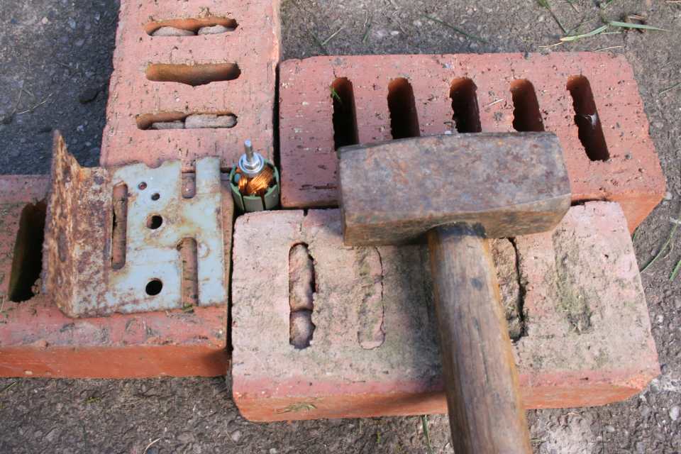
Most of our readers do not have pullers to remove the bearings. With motor 1 I used the low tech solution we developed for the D1L blower. D1L blower page has more details. The slot was really too wide, I later cut a narrower one. A medium hit on the end of the shaft with a 4 pound club hammer drove the bearing to the end of the shaft. A small drift (metal rod) drove out the final part.
Removing the bearing released the brush plate and gave access to the commutator.
Tip: A tap with a heavy hammer is far more effective than a blow with a light hammer.


The commutator of motor 1 was undamaged but had some wear. Distinct ridges and grooves could be felt all the way across the segments. New brushes could have been fitted as is, they would bed in to match the commutator grooves. I preferred to remove the grooves as brushes would bed in quicker and any end to end movement of the shaft could cause slight widening of the brush grooves. Motor 2 commutator was far less worn and did not need sanding.
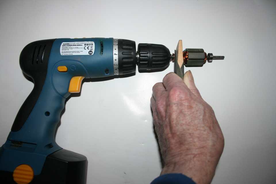
We have no lathe so used an electric drill and a worn 400 grit abrasive disc wrapped round a piece of wood. The wood wedge shape made getting the right width easy. A perfect level finish was not necessary, I sanded off the minimum amount of the copper to remove the grooves. The segment gaps were checked to see they were still undercut before burnishing with a strip of cloth for a good smooth finish. Tip: If the plate had not been removed there is room to reach the commutator with sandpaper wrapped around a thin flat object.
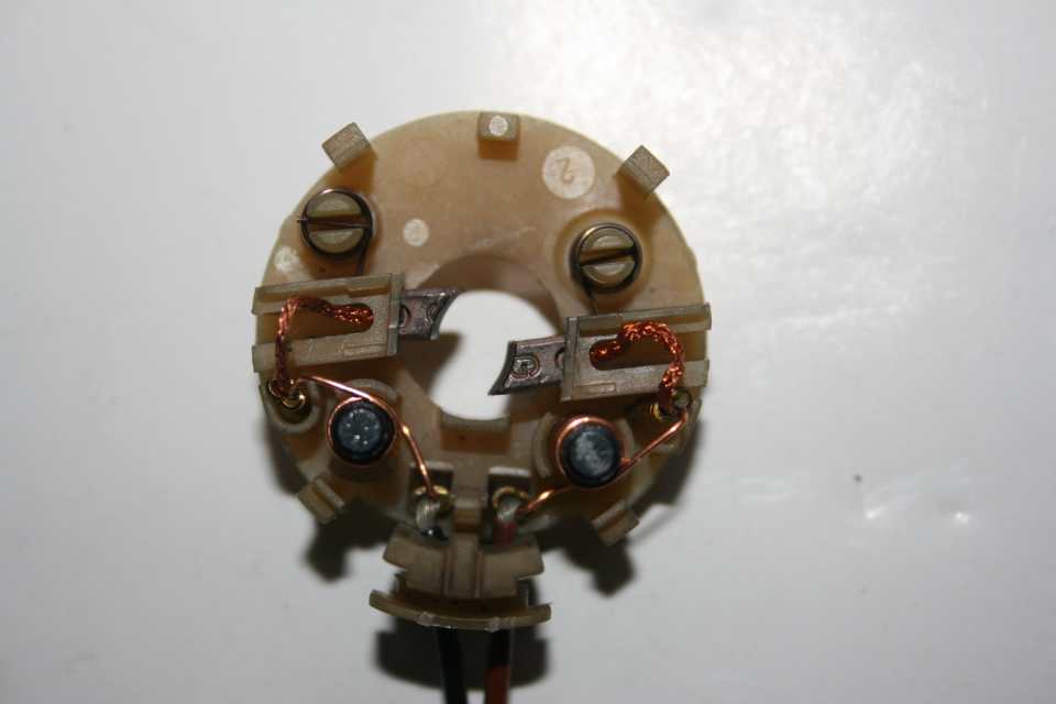

The earlier type replacement brush wires are stiff so when cutting off the old brush wire for these cut it close to the brush, not as shown in following photographs. Two springs, top, apply pressure to the end of the brushes. Wires are joined with compression clips. The two black ferrite rods suppress electrical interference.
I have a hook tool to release the spring pressure when removing or inserting brushes but it was just as easy to use a low tech 30 mm bent safety pin version. The picture shows where to hook the spring.


The brushes are mounted offset to the commutator so the end of the brush needed to be shaped. Using the old brush as a starting guide I found it easier to control the angle using a file instead of sanding. The angle of the point is roughly 60°
Tip: I found it is better to do this after the slots are cut, the wire has to leave the brush at the top when shaped as shown.

This brush had not yet been trimmed or shaped to a curve.
Tip: After pulling the brush spring back lift it vertically, it will rest on the moulding instead of returning to the slot. Be careful not to lift it too far. One brush spring is shown here resting on the moulding.

The brush projected beyond the edge of the plate / plate guide and needed further trimming to 12 mm maximum. Photo also shows the spring resting on the moulding.
Tips: Maximum length depends on the depth and shape of the spring slot, the spring must be freely pushing the brush towards the commutator so it moves as it wears down. One mistake I made when working with the wires on motor 1 was to twist them tightly to stop stray wire ends splaying out. That makes the wire even stiffer. Make sure you insert the brush with the angle the right way round.
Using the old brush as a guide I shaped the curve roughly using a small round file. For final shaping I wrapped fine sandpaper round the shaft of a drill bit and sanded up and down to match the original shape as closely as possible. The motor 1 commutator had a small ridge at each edge which had not been removed during smoothing, the extreme end of the brush was narrowed slightly to avoid the ridges and fit flush on the commutator. The brush will adjust for the ridges as it wears.

I carefully cut two slots with a file and scalpel. The first was so the wire would not project beyond the end of the brush. The cross slot for the spring on the old brush was quite wide, I filed a narrower slot. The wire came loose in many of our early trials destroying the brushes. Then I modified the method so the wire was not central and cut the cross slot slightly away from the wire.
Update 2018 The wires on the Bosh brushes are more secure. I cut the cross slot with a junior hacksaw.

I had previously removed the second bearing. The replacement was extremely tight and needed very heavy hammering down the shaft with the metal plate. When rotated it felt very rough and obviously damaged. An inspection of the bearings showed the inner section was recessed so the plate was only contacting the bearing outer causing sideways pressure on the ball bearings. I had plenty of spares but needed a change to our method.
I searched for something to use as a spacer, an old 2BA nut in the spares box was the right size, roughly M4 size. Surprisingly I also discovered some bearings from the pack of 10 were looser on the end of the shaft than others, two could even be pushed all the way on by hand. Probably the pack are manufacturers rejects. A medium tight one was selected and it moved easily down the shaft with light taps to its final position with the shaft projecting about 21.6 mm.


The cup washer and brush plate were fitted on the shaft before driving the bearing to leave about 18 mm of shaft protruding. I had to take care not to drive it in to too far which could be a disaster if too small a gap was left for removal. To prevent this I temporarily placed a second piece of metal in the gap. The paving slab gave a solid bounce free surface which was better than using a workmate. Four bricks held the rotor securely upright. Bearing was fitted at this stage as its position was not known and it was more convenient for experiments.
Update 2018 Not essential but better to leave installing the bearing till later so that the copper washer can be locked in place.
I was a little careless and lifted the spring too far so it slipped off the moulding and released the tension. I took that opportunity to remove the spring for photographs. Left picture showed how it would look in its final position but it needed more tension, I rotated the spring through 180° and slotted it onto the pillar as shown right.
Then the free end of the spring was rotated anticlockwise, carefully lifting over the obstructions, first one shown left, to its proper position where it entered the slot, right. Re-


Brushes fitted and ready for soldering. I checked the brush springs were properly positioned. The new brush wire was stiffer than the old one so I decided to cut off some of the strands.
Update 2018 The Bosh brush wire is more flexible and does not need thinning.


The crimp connector was pulled free from the moulding and the old wire shortened before soldering to the new wire. The crimp connector was then pushed back into place in the moulding. A quick electrical continuity check between the pins of the 2 pin connector verified the brushes were working ok and it was ready to be put back together.
Airtronic D2 D4 blower motor re-assembly

On motor 1 the plastic cap was hammered onto the shaft until the bearing pressed against the top of its recess. The copper coloured washer had to be left loose as there was no way to lock it into position. It took a little work to get the four catches to lock in. I checked the shaft rotated freely and again checked for electrical continuity.

A very small amount of grease was applied to the crinkled washer before fitting it on the shaft. The shaft fitted easily into the motor body. Tip: If the shaft is pulled back the steel washer can slide off the shaft and adhere to the magnets and not be noticed. Align the slot in the case with the moulding and hold the shaft vertical with the washer end at the top while inserting. The magnets will pull it towards the side but it is easy to guide it into position.

Before bending in the retaining tabs I tested the motor. Pins were inserted into the connector provided electrical contacts. The motor is 9 volts but I started on about 4.5 volts as there was no cooling fan and I wanted the brushes to bed in gently. I had a professional variable voltage power supply otherwise I could have used dry batteries.
Motor 1 worked when tested but was not as quiet or as vibration free as a good working motor. Some noise was not unexpected, the brushes were crudely shaped and it could take time for them to wear to match the commutator. After a couple of hours running I took the motor apart to check the bearings, commutator and brushes. The bearings seemed ok but we have suspicions about their quality. The leading and trailing edges of the brushes had not yet been worn down to match the commutator and there were visible polishing marks on each of the commutator segments but more towards one side showing the brush had not been shaped level. This would be corrected as the brushes bed in. It was as expected so I re-
Motor 2 did not rotate. It would draw current with the rotor in some positions but electrical checks revealed some segments were open circuit. This was not unexpected, the brush housing had melted and the brush was contacting the commutator in an incorrect position. I did not check earlier as the experimental repair procedure was the most important aspect, getting the motor working would have been a bonus.
Donation request
If you have a faulty motor and decide not to repair it please donate it so I can improve repair methods. I would expect to repay the carriage costs.
D3LCC blower motor repair
Dominic Baldwin told us on the D3LCC the shaft of the motor has a spring at the back of the bearing so sliding in a knife had no effect. There was around 10 mm forward movement on the fan, he ended up using a couple of wood chisels and a lot of brute force until it finally popped off. The brushes are fitted directly opposite each other on the commutator of this motor, the bearings were easy removed and are 626zz. Thanks Dominic.

D2 Bearings are 13 mm outer diameter, 4 mm inner, 5 mm thick. Replacements are described as 624Z 4x13x5. I bought 10 for £3 post free from China on ebay Jan 2015. We have some suspicions these are manufacturers rejects and would not buy them again. UK ones with quicker delivery were same price for 2.
D4 bearings are different, inner diameter is 5 mm and the bearing width is 4 mm ie 5x13x4
Thanks Thomas Nilsson for the D4 details.
These new carbon brushes for motor 1 were oversized, nominally 16 x 8 x 6 mm. The old ones measured 5.7 x 3.7 mm. The original length is unknown but guessed as about 12 mm maximum, if too long the spring does not push the brush in. The projection on the end of the new brush where the original spring fitted was carefully trimmed off without damaging the wire. These brushes are relatively soft and were scrubbed by hand on a 400 grit abrasive disk on a flat surface. I kept the wire above centre in the 5.7 mm plane to leave more room for a spring slot. The spring on the brush plate was moved out of the way before checking the brush would freely slide in and out. If the brushes slide into the plate and are tight look for contact marks on the brush surfaces and scrape those away before re-
Tips: I tried several techniques and for me the best method was to sand the 3.7 mm thickness first. I try to only sand one side of these brushes as the outside is harder than the inside so will probably wear less. This may not be possible with some brushes if sanding comes too close to the wire. I found about half of my attempts failed during sanding with detached wires on these brushes but I buy cheap packs of 10 or 20 so not a serious problem. I placed the brush flat on the abrasive and sanded with 20 circular or back and forward movements before rotating the brush 180 degrees and doing another 20. That method helped to keep the sanding even. A scalpel used as a gentle scraper corrected any slope or unevenness. I repeated this until the brushes were 3.7 mm. Then I did the 5.7 mm side. In the following photo the non sanded sides should be on the left and underneath. Digital callipers make measurement simple and were used multiple times during sanding to check for size and flat surfaces.
Update 2018 With motor 2 the Bosh angle grinder brushes 15 x 8 x 5 mm were much better quality and noticeably harder all the way through, both sides can be sanded. They do not have the collar projection round the wire, meaning the wire retention is more secure. Definitely better in several ways than the motor 1 versions and I did both brushes with no failures. I immediately re-
I have left in the details of the earlier brushes in case the Bosh versions are not available.
Final part on fitting the impellors need to be done when we do the next repair.
Due to other interests and a lot of work on the website this part of the webpage is being held and will be completed later.
One item that is important when re-
Pictures showing this are on the Faults page.


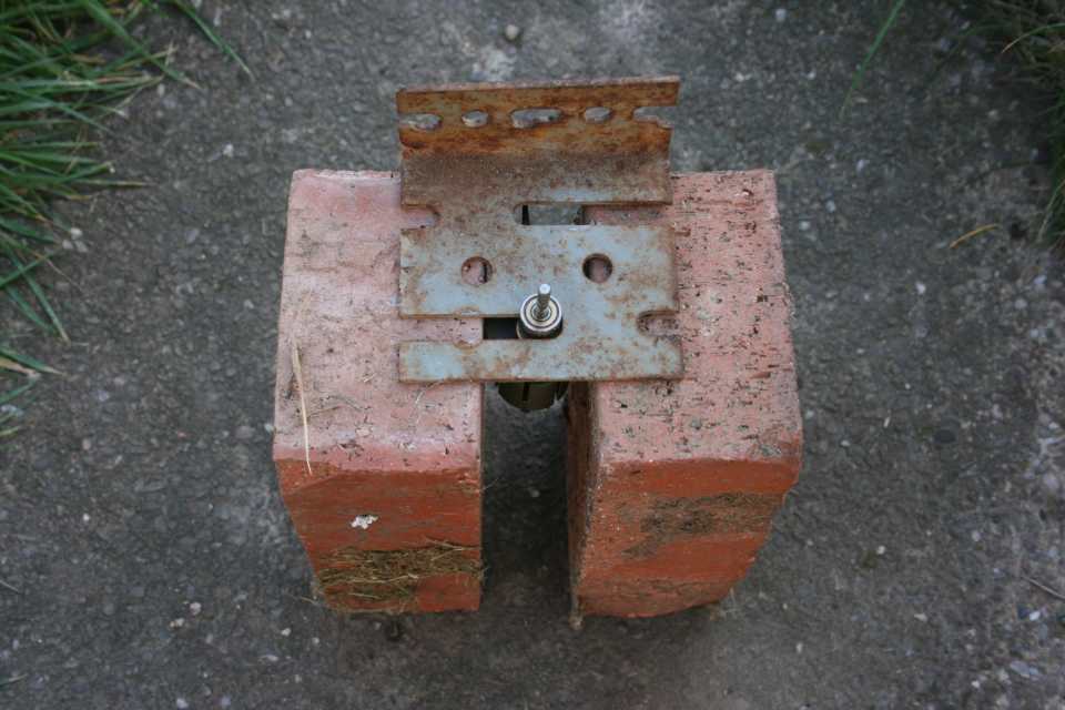
Inset bottom left shows spigot locating in metal washer.
These two pictures by Thomas Nilsson show the spigot that is missing on some pictures of motor 1. The copper washer on my motor was the other way round.
Brushes used for motor 1.
I prefer the Bosh brushes used for motor 2.
REMOVING MOTOR 1 BEARING
This was the first method, an alternative method was used for Motor 2
REMOVING MOTOR 2 BEARING
One bearing on motor 2 had to be removed to release the brush plate so I could repair the melted housing.
It gave the opportunity to try removing using a vice as an alternative to hammering.

My sections of angle iron were 2.5 mm thick, too big for the 1.5 mm gap between the bearing and copper coloured washer. I cut a slot in a 30 mm diameter repair ‘penny’ washer that was 1.5 mm thick.
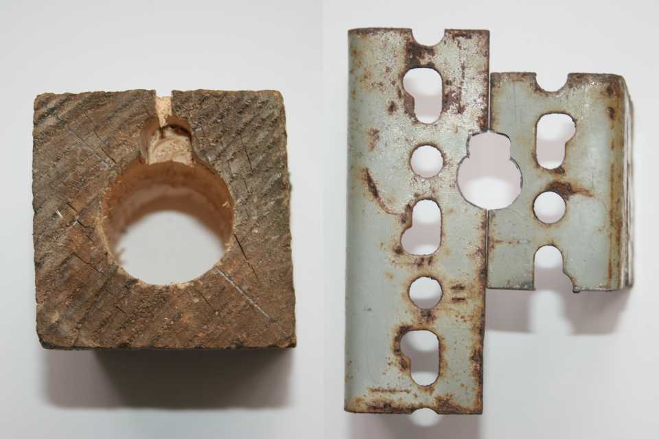
I drilled a 35 mm hole through a 120 mm length of 70x70 mm wood. I cut a hole in the angle iron slightly larger than the copper coloured washer and extended it to fit over the brush plate protrusion.

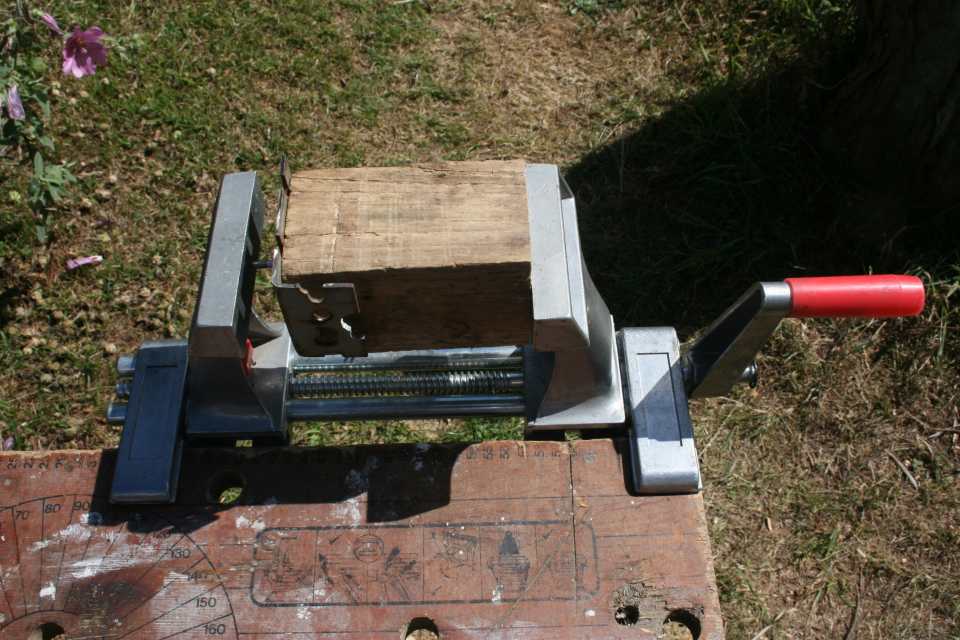
Ready for squeezing in the vice.
However without an extra pair of hands I could not hold everything in position and tighten the vice. After a couple of attempts I resorted to the old method of hitting the end of the shaft with a hammer. The wood base was not solid but the bearing moved over 1 mm up the shaft.
Not the intended solution but what looks good in theory does not always work in practice!
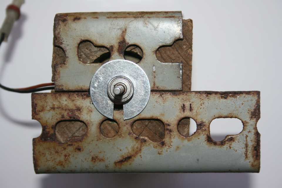
The angle iron would now fit in the gap and I could finish it in the vice as originally planned.
The bearing moved easily up the shaft.
A small drift (metal rod) drove out the final part.


With motor 2 the cap had not been fitted and needed assembling.
If the locking washer does not lock in place bend the edge out a little and try again.
Tip I used a suitable sized socket spanner to press the locking washer into position and keep it level.
The cap needed to be pushed onto the shaft. I had recorded the length protruding before the motor was taken apart, with this motor 16.6 mm
The end of the shaft passed through a hole in the wood, it did not reach the vice jaw. I made repeated measurements on the length of the protruding shaft to ensure I did not squeeze it out too far. 100% precision is not possible, I was happy to accept mine within 0.15 mm of target.