


Le Tonkinois Varnish
B & D Murkin
UK main importers for
Le Tonkinois varnish
Flexidisc sander
Eberspacher Hydronic Service and Repair
Covers D4WSC, D5WSC, D4WS, D5WS, D4WZ, D5WZ models
D3WZ is fairly similar, some details will be published later on a new D3WZ page.
Hydronic 10 and Hydronic M are covered on D10W service page.
The photographs are of a D4WSC but the information covers a number of similar models.
Early versions of these heaters had some differences, see bottom of page.
OEM heaters should either be the same or very similar to service.
We dislike using images copied from manuals so if you do a service please photograph each stage for us. Preferably take the images in high resolution landscape format showing every detail. We can edit images.
Servicing information for these models has been created by combining information from various sources. We did not have any of these to take apart and manuals do not show every detail. We believe the info is accurate but please confirm this. Donation of unwanted or non repairable heaters would be greatly appreciated. Any comments, suggestions or corrections will help improve the site page for other users.
Click on images for better quality.
Disassembling Eberspacher Hydronic D4WSC & D5WSC heaters
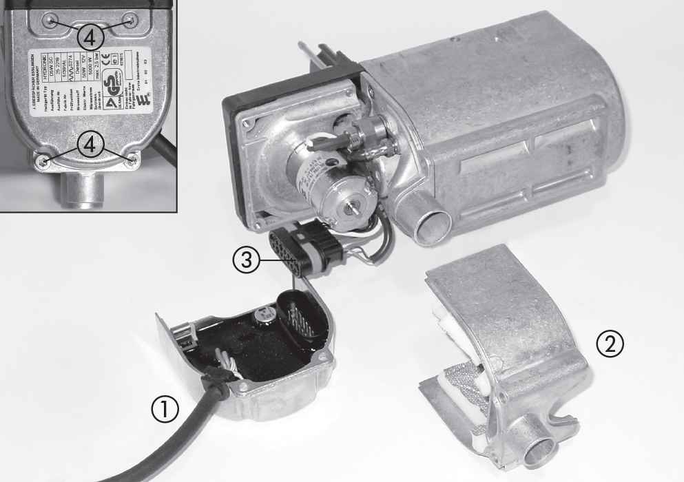
Remove the cover. Other models have no pumps so the first 3 steps will be different but straightforward.
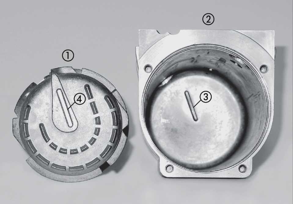
Remove the cover with the water pump.(1)
Routine servicing can be done without removing this cover.
(2) 2-
Water pump and its connector.
Replace the O-
Undo the four M5 Torx screws holding the ECU (4). Upper screws are 10 mm, lower ones 65 mm and 16 mm.
Remove the inlet port with lining (2). Unplug the ECU connector (3), there is a retaining latch.
Combustion air inlet. This part should have a thick lining on the inside but here it is absent.
It is not usually necessary to dismantle these parts completely. If dismantled lubricate O-
Retaining wedge is just visible on left side of ECU connector.
It may not be necessary to remove but the Glowpin (1) Flame sensor (4) and Blower (3) can only be removed if you have a terminal removal tool to release the wires from the 14 pin connector. A friendly garage mechanic may have one in his tool kit. The glowpin socket (2) is retained by a C shaped Bracket which is held in place by the Flame sensor.
Disconnect the fuel hose from the fuel pipe (3). Undo the 3 Torx screws (2). Ease off the cover and fuel pump. The original plastic tie clip might be replaced by a jubilee clip. (picture shows ECU still attached)
Levering the impeller from the splined shaft in the wrong manner can break it, see Blower page before removing. 3 screws are hidden under the impeller. The impeller clearance is 0.3 mm as shown on Faults page. The blower motor is wired into the 14 pin connector.
Undo the 3 torx screws (5) and separate the blower section. Check / replace the gasket (4). The blower wires will only have to be removed if replacing it.
Blower section separated with the wiring. Testing instructions for the motor given in the troubleshooting manual are wrong, speed should be >10000 rpm, not >1000.
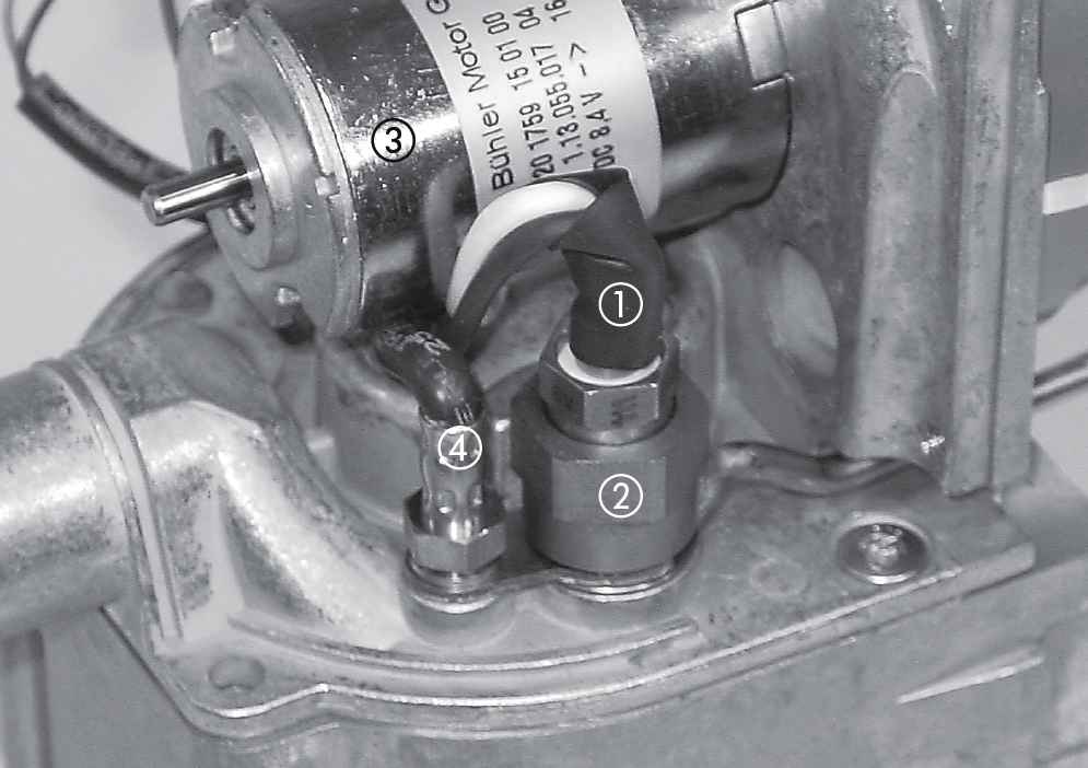
Undo the pressure spring screw (3) and remove the Overheating sensor (1) and Temperature sensor (2). This removes all wiring to the burner / heat exchanger section.
Flame sensor is 1062 ohm at 20°C, 1000 ohm at 0°C ± 10%.
Overheat sensor is 12480 ohm at 20°C, 32540 ohm at 0°C ± 10%.
Temperature sensor has blue wires, Overheating sensor has red wires. 14 pin connector retaining latch is clearly visible. Motor is 8.4 volts.
These parts usually do not have to be separated in a normal service. When refitting the heat exchanger (1) the groove (4) must fit with the stopper (3) in the body. Check heat exchanger fits properly in the body, it has to be pressed firmly into position. Confirm the socket for the overheating sensor matches the location hole in the body.
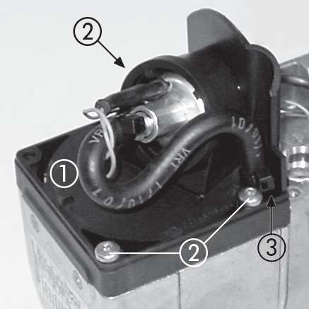
Blower with Flame sensor and Glowpin components removed. It is not necessary to do this for most servicing.
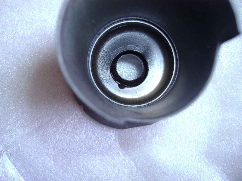
The glowpin screen fits inside the glowpin socket (2) and can be removed from this side without removing the glowpin. Clean the glowpin and fit a new screen. The welding spots should be at the bottom. Knobbly deposits on the glowpin indicate water in the fuel.
Additional information:
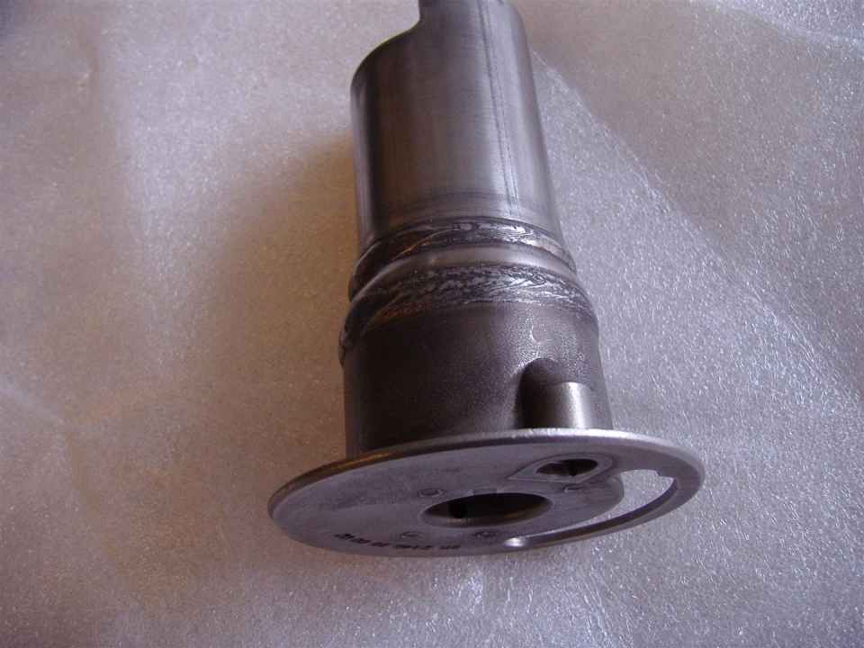
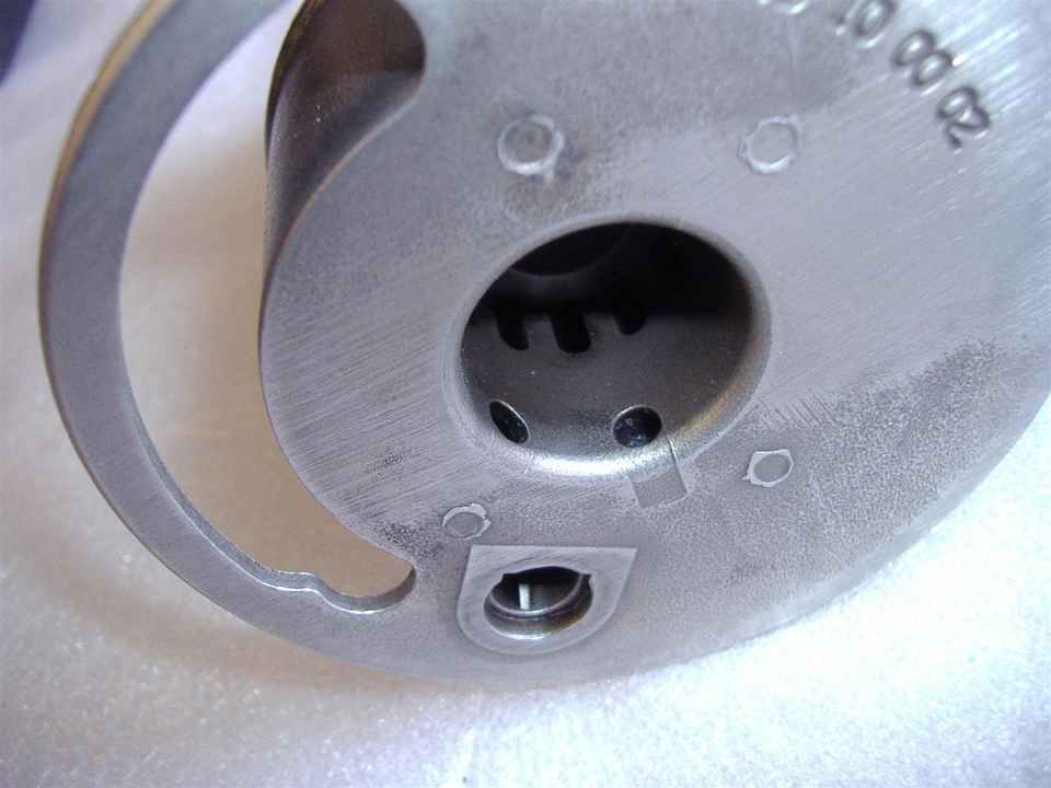
Combustion air is blown by the impeller through the hole (1) and swirls into the centre where it enters the burner. Exhaust gasses exit the burner into the exhaust port (4), they come into contact with the flame sensor (3).
In his video Steve mentions some holes in the burner are difficult to see and to make sure they are clear. I suspect the holes shown here are not the holes he mentions, usually burners have some small ventilation holes in the glowpin housing (bottom hole). Confirmation and photos of position of holes wanted please.
Some burners may require chemical or industrial ultrasound cleaning as a mechanical clean cannot reach hidden parts. Any chemical cleaner can be dangerous, always follow manufacturers instructions. For health and safety reasons we make no recommendation but many users clean with caustic soda.
View into far end of burner.


Inside the burner is a wire mesh, probably similar to this one shown in a cutaway model MII. The mesh can become clogged by deposits and can deteriorate with prolonged use, see the D4 example in autopsy pages.
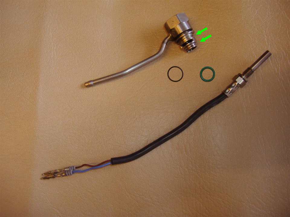
The upper arrow points to a groove in the glowpin socket for the thin O-

The inside of the heat exchanger is fully accessible for mechanical cleaning, chemical cleaning can also be used.
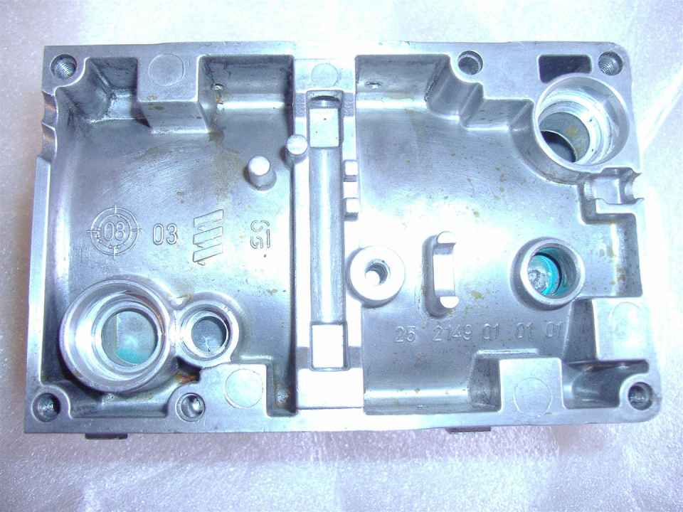
The heater body is the outer layer of the water jacket. Water flows inside it over the heat exchanger. Water inlet (1), Water outlet (2), Overheating sensor hole (3). Temperature sensor hole (4).
Pull the burner (3) out of the heat exchanger (2). Replace the gasket (4). For most services it will not be necessary to split the heat exchanger (2) from the body (1), to do so temperature sensors (6,7) must have been previously removed, then press the heat exchanger out with a screwdriver through the water inlet.


The fuel pump has a filter in the base that should be checked as part of the service. The pump (1) should pull out of the holder (2).
The holder should not need to be removed but if it is when refitting ensure the recess (2) on the holder slots into the connection web (3).
Fuel filter in a similar D1LCC pump recess. You may have to use a pointed implement dug into the side of the filter to remove it.


Unscrew the 17 mm nut on the fuel pump inlet, left. Do not unscrew the nut at the end closest to the terminals.
D1LCC pump with filter removed.
Badly neglected filter with its replacement. The condition of this filter is not normal, the filter can usually just be checked for debris and does not need to be changed.


Old parts.
The glowpin screen looks in very bad condition. It should always be renewed as should the gaskets. The burner gasket acts as a thermal barrier so don't try DIY gaskets like cardboard.
Eberspacher Hydronic service kit.
It covers all 6 models. This set does not have the large and 2 small black O-
In December 2014 servicing kits on Ebay were £37.50 or £47 with the 3 O-
D3WZ set is similar but a different size.

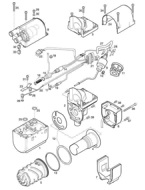
Hydronic D4WSC D5WSC parts drawing.
Hydronic D4WSC D5WSC main parts.
Eberspacher Hydronic Operation.
The water pump runs continuously from switch on until the heater is switched off. The heater checks the glowpin and fuel pump before starting. It must also check the temperature and overheat sensors and water pump but when it does so is not specified. The motor speed is continuously monitored and if it falls below 40% of nominal speed for 60 seconds heater is switched off. The temperature thresholds are permanently programmed in the Electronic Control Unit (ECU). When the water exceeds about 30°C a relay is switched on for controlling external fans, it switches off below 20°C. Once the temperature reaches 80°C the heat output is controlled automatically, switching between high low and standby(off) as shown. The heater will make two start attempts as described on the faults page. Flame out failures are also treated as described on the faults page as are other faults. Fault codes are on the Fault Codes page. The troubleshooting and repair manual describes how the heater operates in slightly more detail.
Fuel quantity test as described on fuel page in cc (or ml) should be between:
D4WSC 7.3 to 7.9, D5WSC 8.5 to 9.0
As far as I can tell these details apply to all of the models.


These have no internal pumps so upper parts are different, otherwise servicing is the same as D4WSC, D5WSC.

New glowpin screen. Fit it with the 5 welds at the bottom.
D4WS, DW5S.
D4WZ, D5WZ.

This early Hydronic heater I found on a foreign site shows the holes for the 3 hidden screws. The burner is different. Later models had several design changes, see bottom of page.

If heat exchanger is disassembled replace the O-
D4WSC taken apart. Many photos on this page are from an Ebay seller, thanks.
On top of the D4WSC DW5SC heater is a bleed valve to release trapped air from the system after servicing.
The central hole through the heater is for a fixing bolt.
Early models of these heaters, photo of one shown earlier, had some differences to the later versions. We are aware of the following.
The glowpin had terminals like the one shown in the D10W page.
The fuel pipe went straight into the burner so the glowpin screen was not replaceable. A similar burner is on the D3WZ page.
The connector to the ECU was rectangular.
Youtube video http://www.youtube.com/watch?v=14SUSxfPHPY shows an early D4WSC Hydronic model being taking apart. [useful video but next time Steve try to
1) Get the model names right, 2) get the part names right,
3) Mention the glowpin screen, 4) Show where in the burner the holes you describe are located.]
After mechanical or chemical cleaning the burner and heat exchanger the heater can be re-
Assembly should be the reverse of taking apart. Always fit a new glowpin screen and gaskets.
A very small number of DW4SC and D5WSC are installed with a connecting pipe in place of the internal fuel pump. This allows the pump to be re-
For refilling or topping up use a 10 to 50% antifreeze mixture, it also prevents corrosion.
Manuals do not show every detail so please confirm which instructions are ok or have errors.
Also as requested at the top of the page if you do a service please fully photograph each stage for us.
Preferably take the images in high resolution landscape format showing users every detail.
We want to enable users to do the full service in their mind before they even remove the heater.
Any corrections, suggestions or comments will help improve the site page for other users.


The other photos are new or full cleaned so some real life pics to restore some reality.
Degraded fuel caused this D5WSC to clog up and fail within a month of a full service.
Eberspachers can get in this state very quickly, see fuel problem page. Smelly fuel soaked soot, very soft, much would have fallen off during removal. Photos Craig Cheek